Schematic Tutorial
Revolution EDA Schematic Editor
This guide targets designers already familiar with legacy circuit schematic capture tools (for example Cadence Virtuoso). Revolution EDA follows the same core workflow: place instances, wire, annotate, define pins, generate symbols, and netlist/simulate at zero cost and full access to source code without having to worry about software licence fees.
Quick Orientation (for Virtuoso Users)
- Library Browser: similar to a library manager; open schematic cellviews from the library browser.
- Instance Placement: press
ito place symbols;qopens the instance properties. - Wiring: press
wto draw orthogonal wires. Wires snap to pins, auto-merge with other overlapping nets, and form junction dots when two nets are orthogonal and one ends on the other. When a junction dot is created, one of the nets might be split at that point. - Pins: press
pto create schematic pins (for hierarchy and symbol generation). - Hierarchy:
Go DownandGo Upbehave like standard hierarchical editing. - Netlisting/Simulation: accessible from
Simulationmenu; supports switch/stop lists and config views.
Virtuoso to Revolution EDA Mapping
The table below maps common Virtuoso schematic actions to Revolution EDA equivalents.
| Virtuoso Action | Revolution EDA Equivalent | Notes |
|---|---|---|
| Add instance | Create -> Instance... or press i | Select symbol view, then click to place |
| Edit properties | Select item and press q | Instance, pin, wire, or text |
| Wire | Create -> Wire or press w | Orthogonal wiring, auto-junctions |
| Place pin | Create -> Pin or press p | Direction: Input/Output/InOut |
| Net label | Net Properties on selected wire or press ‘l’ | Names propagate along connected net |
| Highlight net | Tools -> Highlight Net | Hover to highlight connected net |
| Go down hierarchy | Edit -> Hierarchy -> Go Down or Shift+E | Choose schematic or symbol |
| Go up hierarchy | Edit -> Hierarchy -> Go Up | Returns to parent view |
| Generate symbol | Create -> Create Symbol... | Uses schematic pins |
| Create netlist | Simulation -> Create Netlist... | Switch/stop lists supported |
| Run simulation | Simulation -> Simulation Environment... | Requires revedasim plugin |
Typical Design Flow
- Create or open a schematic view from the Library Browser.
- Place instances with
Create -> Instance.... - Wire the circuit with
Create -> Wire. - Add pins for hierarchy and symbol generation with
Create -> Pin. - Annotate with text labels as needed.
- Generate a symbol using
Create -> Create Symbol.... - Create a simulation testbench using Revolution EDA Simulation and Analysis Plugin (Revedasim).
- Alternatively, just netlist using
Simulation -> Create Netlist...and use a third-party tool for circuit simulations and verification.
Menu Actions You Will Use Most
This section summarizes the most common schematic editor actions by menu.
File Menu
The File menu handles saving, printing, and exporting your schematic designs.
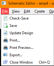
File -> Check-Save: validates the schematic and saves it to disk.File -> Save: saves the current schematic without validation.File -> Update Design: reloads all referenced cells from disk, useful after external changes.File -> Print...: opens a print dialog to send the schematic to a printer.File -> Print Preview...: shows a preview of how the schematic will appear when printed.File -> Export...: exports the schematic as an image file (PNG, JPEG, etc.).File -> Close Window: closes the current editor window.
File menu actions and shortcuts:
| Action | Shortcut | Notes |
|---|---|---|
File -> Check-Save | None | Validates design rules before saving. |
File -> Save | None | Quick save without validation. |
File -> Update Design | None | Refreshes all cell references from disk. |
File -> Print... | None | Standard print dialog with page setup. |
File -> Print Preview... | None | Preview print output before printing. |
File -> Export... | None | Export as image for documentation. |
File -> Close Window | Ctrl+Q | Closes the editor; prompts to save if unsaved changes. |
View Menu
The View menu controls how you see and navigate your schematic.
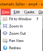
View -> Fit to Window: zooms and pans to show the entire schematic.View -> Zoom In: increases magnification for detailed work.View -> Zoom Out: decreases magnification to see more of the design.View -> Pan View: enables mouse-based panning of the view.View -> Redraw: refreshes the display, useful if rendering issues occur.
View menu actions and shortcuts:
| Action | Shortcut | Notes |
|---|---|---|
View -> Fit to Window | F | Fits entire design in view. |
View -> Zoom In | None | Step zoom in; use mouse wheel for continuous zoom. |
View -> Zoom Out | None | Step zoom out; use mouse wheel for continuous zoom. |
View -> Pan View | None | Click and drag to pan; middle mouse button also pans. |
View -> Redraw | None | Forces screen refresh. |
Edit Menu
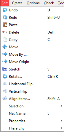
-
Edit -> Net Name: Enter the net name string in the dialogue and then select a net to set its name. -
Edit -> Properties -> Object Properties: inspect or edit properties for the selection. Depending on the instance, the use also can inspect the instance attributes for the instance, but not edit them.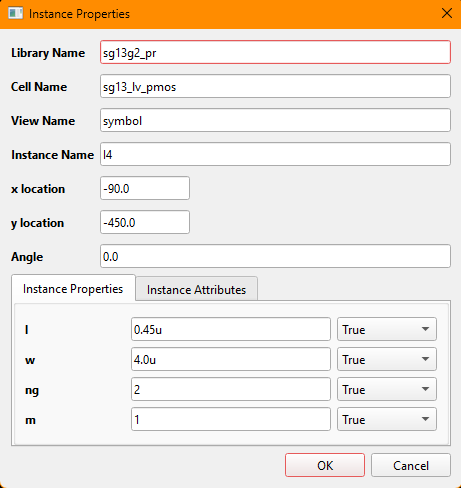
-
Edit -> Move: move selected items interactively in the canvas. Press on an item or select multiple items by drawing a selection rectangle by pressing shift+left mouse button. Then pressmkey to move the item(s), press the left mouse button and carry the item(s) to their new location and release the left mouse button. -
Edit -> Move By: apply a precise X/Y offset to the selection. Select an item on the schematic, selectMove Bymenu and enter the displacement in x and y dimensions. As the displacement values are snapped to the schematic grid, the actual displacement might be different from the intendend values.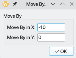
-
Edit -> Move Origin: reposition the view origin for coordinates. After selecting the menu item, click and release the left-mouse button at the point that will be the new origin of the schematic. Note that it will be snapped to the nearest grid point and thus might differ from the left mouse button release point. -
Edit -> Rotate: rotate the selected items around the pivot point. Select an item on the schematic, clickRotatemenu item and click once again on the item to select the origin of rotation. -
Edit -> Align Items: align edges or centers using the align dialog.
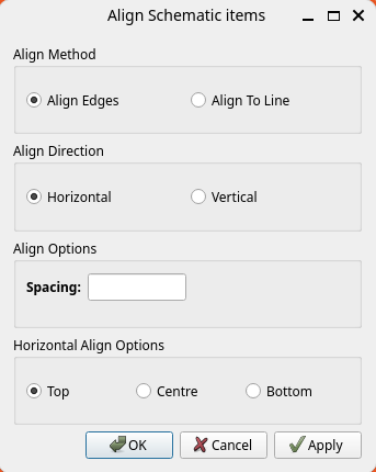
There are two methods of alignment:
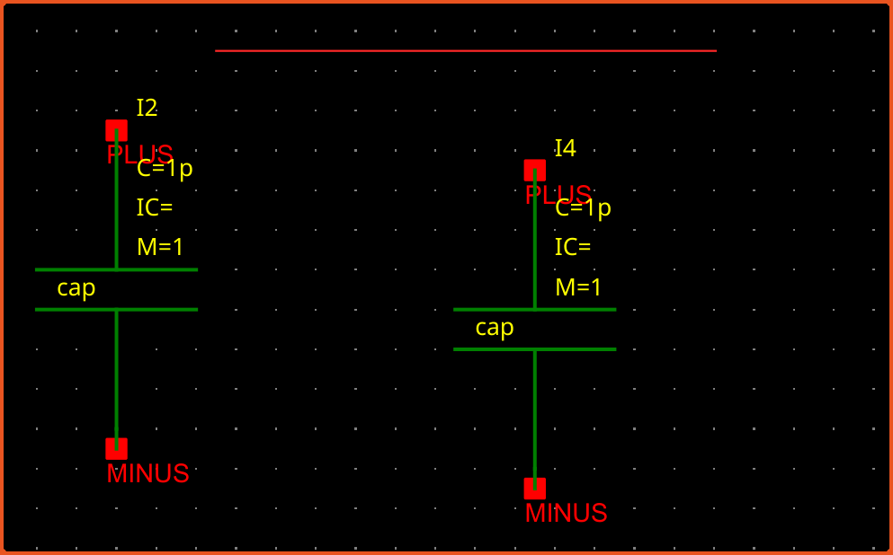
- Align Edges: Select more than one item and then decide alignment direction (horizontal or vertical) and optional spacing between items. You also need to select how the items should be aligned: top, centre or bottom. Then press
OKto align the items. If the alignment is wrong, you could undo it by pressingukey. - Align To Line: Again select more than one item. If a horizontal alignment is required draw a horizontal line or draw a vertical line if a vertical alignment is desired. Click left mouse button at the start of the alignment line and pull the mouse cursor to the desired end point and release the left mouse button. A thin red line should be drawn. The length of the alignment guide line is not important.
Similarly to Align Edges option, the user can select alignment direction (horizontal or vertical), spacing between the items, and alignment edge (top, centre, bottom for horizontal alignment and left, centre, right for vertical alignment).
Edit -> Horizontal Flip: Flip selected items horizontally.Edit -> Vertical Flip: Flip selected items vertically.Edit -> Selection: This menu has two submenus:Select All: Select everything on the schematic.Unselect All: Unselect everything on the schematic.
Edit -> Net Name: This menu item opens a small dialogue so that the user can enter the net name. Once the dialogue is closed by pressingOKbutton, a net can be chosen to assign name to. Note that nets can also be named using the properties dialogue.
Edit Menu (Hierarchy)
Edit -> Hierarchy -> Go Down: open selected instance in a child view. A dialogue window opens allowing the user to choose one of the available views to descend to. The user can also useShift+ekey combination to go down an instance. The view types that can be descended into are:- Schematic: Opens the schematic editor for the instance.
- Symbol: Opens the symbol editor for the instance.
- Verilog-a: Opens the Verilog-a editor for the instance.
- Spice: Opens the spice editor for the instance. Schematic and Symbol editors have additional buttons on their toolbars for moving back up to hierarchy when they are started with hierarchy operation. Verilog-a and Spice editors also offer the import dialogue when the editing is finished and the window is closed.
Edit -> Hierarchy -> Go Up: return to the parent schematic. Schematic view is updated if there is a change in the instance symbol.
Edit menu actions and shortcuts:
| Action | Shortcut | Notes |
|---|---|---|
Edit -> Undo | U | Reverts the most recent schematic edit in the undo stack. |
Edit -> Redo | Shift+U | Reapplies the last undone operation. |
Edit -> Paste | None | Inserts the last copied selection at the cursor location. |
Edit -> Copy | C | Copies the current selection for pasting. |
Edit -> Delete | Delete | Removes selected items from the schematic. |
Edit -> Move | None | Starts interactive move mode for the selected items. |
Edit -> Move By | None | Moves the selection by a precise X/Y offset. |
Edit -> Move Origin | None | Repositions the view origin used for coordinates. |
Edit -> Rotate | Ctrl+R | Rotates the selected items around the current pivot. |
Edit -> Stretch | S | Stretches wires or shapes by dragging a segment. |
Edit -> Flip Horizontal | None | Mirrors the selection across a vertical axis. |
Edit -> Flip Vertical | None | Mirrors the selection across a horizontal axis. |
Edit -> Align Items | Shift+A | Aligns selection edges or centers using the align dialog. |
Edit -> Selection -> Select All | Ctrl+A | Selects every item in the active schematic view. |
Edit -> Selection -> Deselect All | None | Clears the selection without changing geometry. |
Edit -> Properties -> Object Properties | Q | Opens the property dialog for the selected item(s). |
Edit -> Net Name | L | Assigns or edits the name of the selected net. |
Create Menu
-
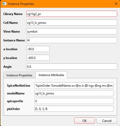
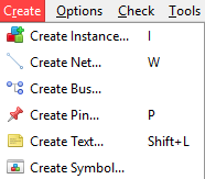
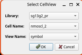
Create -> Instance...: open the symbol selector and place an instance on the schematic. The instance is normally a symbol. UsingSelect CellViewdialogue, the user can choose the design library, cell and cellview to instantiate the desired symbol. Instance will follow the mouse cursor and will be placed at where left-mouse button is released and immediately another instance of the same symbol will follow the mouse cursor. If the user wants to stop the instantiation process at that time,esckey will return to the selection mode. -
After placing the instance on the schematic, the user can change the instance properties by selecting the instance and pressing
qkey or selectionEdit -> Propertiessubmenu.Like nets, an array of instances can be created using array notation for the instance name:
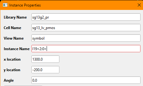
Such an instance array will be expanded when netlisting to create a list of instances between the two instance terminals.
-
Create -> Net: enter wire mode and draw orthogonal connections normally between instance pins. You can name the nets usingEdit-> Net Namemenu item, pressinglkey or using net properties dialogue by selecting the net and pressingqkey.Net behaviour highlights:
- Orthogonal routing with automatic bends
- Snap-to-pin and snap-to-net
- Collinear merge into a single segment
- Automatic junction dots on T-connections
-
Create -> Bus: enter a bus, i.e. an ordered bundle of wires. Nets and busses are interchangeable. Busses are drawn wider and have normally more than one wire bundled together. A bus is indicated with bus notation:bus_name<high:low>orbus_name<low:high>. -
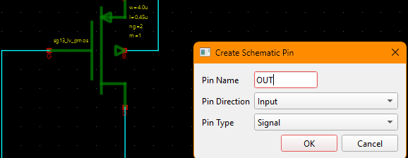
Create -> Pin: place a schematic pin with direction (Input/Output/InOut). Like busses, a schematic can also have a vector notation to connect indicating more than one pin is bundled.
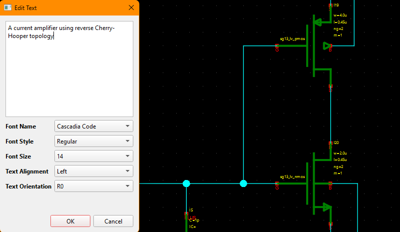
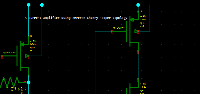
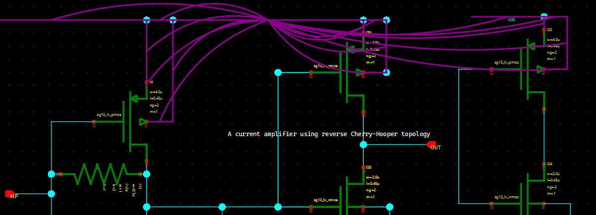
Create -> Text: place a text annotation on schematic to aid the documentation. Select the menu item or pressShift+Lkey combination to openEdit Textmenu. Write your annotation text in the provided space. Your text can have more than one paragraph and text breaks.
Unlike legacy software, Revolution EDA can use any fonts installed on your computer at all available font sizes.
 |
 |
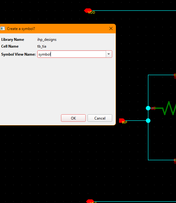
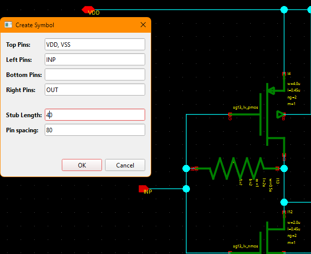
Create -> Create Symbol...: generate a symbol view from the schematic. The schematic pins will be used to generate symbol pins.
A symbol for the schematic can be created using this menu item. The schematic pins will be used to generate symbol pins. The side of the symbol pins, their spacing on each side and the length of pin stubs can all be specified.
 |
 |
There are two important points:
- Symbol view name should include symbol in it. Thus
symbol,1symbol, orsymbol_2are all valid names, butsymbois not a valid symbol view name. - Try to be consistent in stub lengths and pin spacing within a design library.
Options Menu
The schematic editor inherits the Options menu from the base editor window.
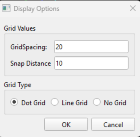
Options -> Display Config...: configure display options for the editor view.Grid Spacingrefers to spacing of of the grid dots at the largest zoom of the schematic. The instance and nets can only be drawn on that grid to ease the alignment of the instances, nets and pins.
Snap Distance is the distance where nets are snapped to symbol or schematic pins.
Both of these settings are saved to schematic file and will be reloaded with the schematic.
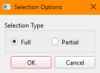
Options -> Selection Config...: configure canvas selection behavior. The selection behaviour configured by this dialogue refers to how elements on the schematic are selected with selection rectangle:
- When
Fullradio button is selected, only items whose selection box fully covered by the selection rectangle will be added to the selection set. - When
Partialradio button is selected, items whose selection box partially overlaps will also be added to the selection set.
Tools Menu
-
Tools -> Read Only: Toggling this menu will lock the schematic to editing. To unlock the schematic, unlock the menu item. -
Tools -> Highlight Net: enable when checked is used to toggle hover-based net highlighting. When this menu item is toggled and cursor is hovering over a net, purple flight lines will be drawn to all other nets that is connected to that net by other wires or by name:
-
Tools -> Renumber Instances: This menu starts the process of renumbering of all schematic instances. This might be needed when the instance names could be repeated among different instances, making some operations like netlisting problematic. -
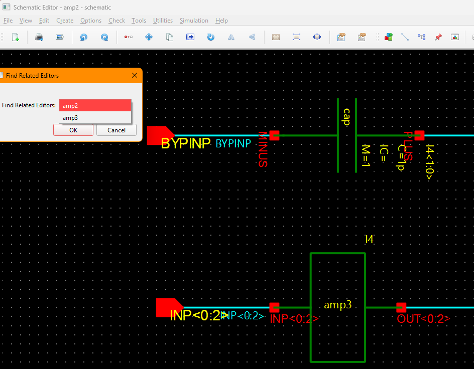
Tools -> Find related editors: When the user goes down a symbol to open related schematic, there might be more than a few schematic editor open depending on the hierarchy depth. Moreover, there could be schematic editors open that are not related to that design. This menu item opens a dialogue that allows the user to choose and highlight any schematic editor that was opened as a part of hierarchical editing.
Context Menu (Right-click on Item)
Right-clicking a selected item in the schematic opens a context menu with common edit and hierarchy actions.
| Action | Shortcut | Notes |
|---|---|---|
| Copy | C | Copies the selected item(s); paste with Edit -> Paste. |
| Move | None | Starts interactive move mode for the current selection. |
| Move By… | None | Opens precise X/Y displacement dialog for selected item(s). |
| Vertical Flip | None | Mirrors selected item(s) across the horizontal axis. |
| Horizontal Flip | None | Mirrors selected item(s) across the vertical axis. |
| Rotate | Ctrl+R | Rotates selected item(s) around the chosen pivot. |
| Delete | Delete | Removes selected item(s) from the schematic. |
| Object Properties… | Q | Opens the object properties dialog. |
| Select All | Ctrl+A | Selects all items in the active schematic view. |
| Unselect All | None | Clears current selection. |
| Ignore | None | Toggles netlist ignore for selected symbol instance(s). Ignored symbols are commented out during netlisting. |
| Go Down | Shift+E | Descends hierarchy into selected instance (schematic/symbol/veriloga/spice view). |
Notes:
Ignoreapplies to schematic symbol instances. If non-symbol objects are selected, this action has no effect on netlisting.Go Downis meaningful when an instance is selected.
Simulation Menu
Simulation -> Create Netlist...: export a netlist for the current view. At the moment, SPICE like netlists are supported. Spectre/VACASK type netlist support is forthcoming.
Revolution EDA can use two types of views for netlist creation:
-
Schematic View: The netlisting of a schematic view is managed through switch view list and stop view.
- Switch view list: preferred view order (schematic vs veriloga vs symbol)
- Stop view: stop traversal at a given view (for example
symbol)
-
Config view: Config view is created through Config Editor which allows cellview selection for netlisting per cell.
For example, a schematic cellview can be used for the initial stages of the design, while an extracted cellview as a SPICE netlist can be created for final verification of the block.
There is also the option of netlisting the circuit as SPICE subcircuit.
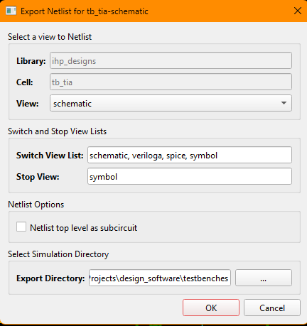
Under the selected export directory, the netlist will be placed at exportDirectory/libraryName/cellName/cellviewName directory as cellName_cellviewName.cir.
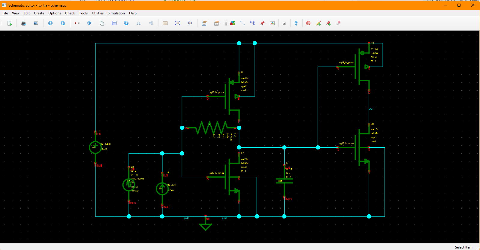
For example, let’s assume that you are netlisting this schematic cellview: Library Name: ihp_designs Cell Name: tb_tia Cellview Name: schematic
And you have selected exportDirectory as /home/user/reveda_exports. The netlist will be placed at the following path:
/home/user/reveda_exports/ihp_designs/tb_tia/schematic/tb_tia_schematic.cirSimulation -> Simulation Environment...: open simulation UI (requiresrevedasimplugin).
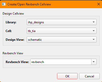
Similar to Create Netlist... menu item, this menu allows you to use schematic or config celviews to create a revbench cellview.
A revbench cellview collects all the information necessary to run a simulation for a testbench. Among others, the user can:
- Setup simulation analyses.
- Import variables from the testbench schematic.
- Select simulator path and number of concurrent runs.
- Select output signals (node voltage or terminal current)
- Model libraries.
- Included files.
- Plot simulation outputs.
- Backannotate transient, DC and AC analysis outputs.