Config Editor
Revolution EDA also offers the ability to create a config view to control the netlisting process. Using a config view, the designer can decide which view will be used in the netlist process, e.g. schematic, veriloga, spice or symbol. Over time other hardware description languages will be also incorporated.
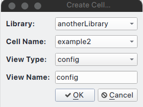
Config view is created like any other cell view. Just start the Create Cell View dialogue as
discussed above and selected config as view type and enter a view name that has config
string in it.
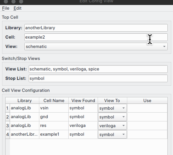
A new dialogue will be displayed for the config view specific information. It will ask which cell view config view will be based on and the default preference order of the cellviews for netlisting, i.e. view list field in Switch/Stop Views box. The dialogue has already default values displayed under the View Found column. Under View To column, a combo box can be used to change the cellview to be used in the netlisting process.
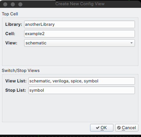
After making desired changes in the dialogue, if any, the designer should press OK button.
Now, the config view editor window will be shown. At first, window will not have any fields
displayed. Under File menu, select Update menu item and the Cell View Configuration box
will display all the cells in the design and default view to use for netlisting.
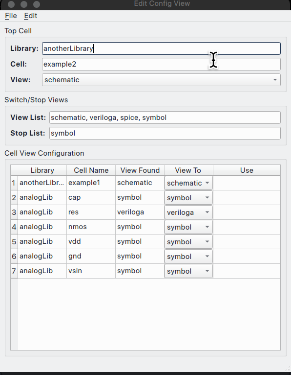
There are two ways of changing the cellview to be used in the netlisting process:
-
The user can change the order cellviews in the View List field and select
File->Updatemenu item. The cellview under the View Found column will change according to the precedence set by the order of the views in View List field. -
-
For each cell, the user can select the cellview to be used for the netlisting. Note that changing a cellview with with hierarchy under it, will change the views shown in the config editor after triggering
Updatemenu item.
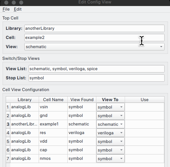
In this example, let’s choose symbol view for example1 cell and trigger Update. Now, none of the cells under the example1 cell schematic cellview show up because we chose symbol view.
Netlisting a circuit using Config View
Now, let us compare two different netlist created by two different config cellviews. In this case, where schematic view is used for example1 cell versus symbol cellview is used for the same cell.
Save the config view above using File menu and Save option and open the schematic view (
It will be soon possible to netlist directly from config view editor.) Once again,
select Create Netlist… menu item under Simulation menu. The Export Netlist dialogue will
be displayed. Select config view instead of default schematic view and press OK. Make sure
that Export Directory is correct. The new netlist file will be created
with <cellName>_<viewName>.cir pattern:
**********************************************************************************
** Revolution EDA CDL Netlist
** Library: anotherLibrary
** Top Cell Name: example2
** View Name: schematic
** Date: 2024-03-16 23:04:24.408427
**********************************************************************************
*.GLOBAL gnd!

XI0 example1 net0 intNoe
XI1 example1 intNoe net1
Yres I4 net1 gnd!  resModel 1k
VI2 net0 gnd! PULSE( 1 1m 1k 0 0 0  )
.END
.MODEL resModel res R = 1
*.HDL /home/eskiyerli/OneDrive_reveda/Projects/RevEDA/exampleLibraries/analogLib/resVa/res.va
Note that netlister has not traversed down the example1 cell and used veriloga view for the resistor.
Now change the View To combobox for example1 cell to schematic cellview and res cell to symbol cellview and save the config cellview. If the netlisting is redone using config view, the netlist will change following the template set in config cellview:
**********************************************************************************
** Revolution EDA CDL Netlist
** Library: anotherLibrary
** Top Cell Name: example2
** View Name: schematic
** Date: 2024-03-16 23:07:51.161492
**********************************************************************************
*.GLOBAL gnd!

XI0 example1 net0 intNoe
.SUBCKT example1 INP  OUT
RI1 net0 drain 1k
CI5 net0 drain 1p 0
CI8 OUT drain 1p 0
MI7 drain INP gnd! gnd! nmos w=2u l=0.18u nf=2  as=560n m=1
.ENDS
XI1 example1 intNoe net1
RI4 net1 gnd! 1k
VI2 net0 gnd! PULSE( 1 1m 1k 0 0 0  )
.END
In this case, example cell is traversed down to schematic view and that cellview is netlisted as subcircuit.
Config Editor offers a level of functionality that is still missing in some leading commercial EDA software.