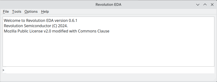
Main Window
Revolution EDA window is the first window an user interacts. At the moment, Tools, Options
and Help menus are usable. Revolution EDA main window also includes a Python REPL interpreter.
Python statements can be input at > prompt. Revolution EDA API is not yet stable
but the user can still access all the power of a Python interpreter.
Tools Menu
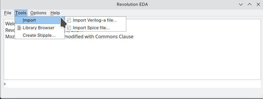
Tools menu has currently three sub-menus: Import, Library Browser, and Create Stipple.
Import Menu
Import Menu is used to import and create symbols for Verilog-a modules and SPICE/Xyce subcircuits.
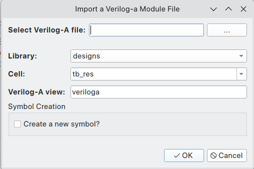
Verilog-a import
Selecting Import Verilog-a file… menu item will display a dialogue
titled Import a Verilog-a Module File dialogue. With this dialogue, the user can select, the
file that has a single Verilog-a module, the library the module will be imported, the cell name
and cellview name. Note that cell name field is editable, and thus a new cell name can be input
as well as selecting one of the existing cells. The cellview name field should also be filled.
The important point is that cellview name should include veriloga in the string. If a new
symbol is to be created, Create a new symbol? checkbox can be checked. A symbol should be
created to be able to use the Verilog-A module in creation of circuit netlists. Note that the
veriloga cellview is in fact a JSON file with a link to Verilog-A module file which is copied to
be under cell directory.
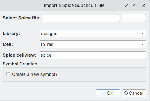
Spice Import
Similarly, selecting Import Spice File…menu item will lead to a dialogue
titled Import a Spice Subcircuit File. Once again, the user can decide if a symbol will be
created for the imported subcircuit. It is advised to create a symbol when the subcircuit is
first imported or the subcircuit pins are changed in any way such as the names or the order.
Symbol Creation
While either importing a Verilog-A module or a SPICE subcircuit, a new symbol can be created. If the new symbol creation checkbox is checked, a new dialogue for naming the to-be-created symbol is displayed:
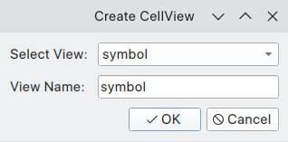
Once again, the chosen view name should include symbol in the string. Click OK and now a new
dialogue to choose pin locations and stub size and the spacing between pins will be displayed:
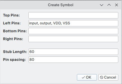
Our advice is not to change stub length and pin spacing values between symbols to keep consistent within a design library. Of course, you could assign subcircuit pins as you see fit between top, left, bottom and right sides. A basic symbol is created ready to be edited further.
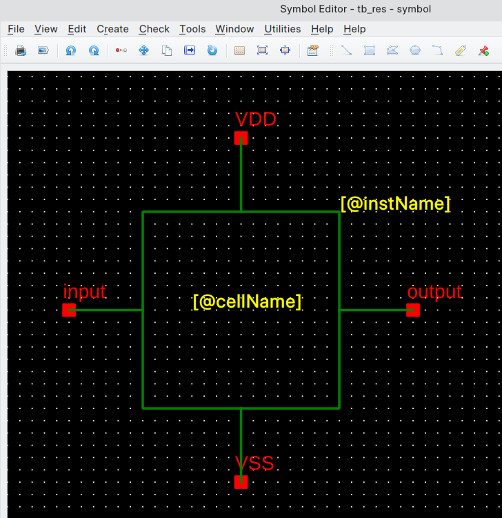
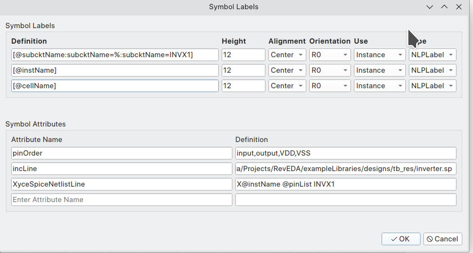
This symbol has in this example three attributes [^1]:Attributes will be further explained in the symbol editor section.
that is needed for the inclusion of a spice subcircuit in SPICE-like netlist:
- XyceSpiceNetlistLine: This attribute is checked when netlisting the symbol in a schematic. It defines the template for the netlisting.
- pinOrder: Pin order defines the order of the pins so that they can replace
@pinListfield inXyceSpiceNetlistLinein the correct order. - incLine: The include line is needed so that the simulator can add the subcircuit in the netlist.
Verilog-A module symbol
The following attributes will be added to a symbol created by importing a Verilog-A module:
- XyceVerilogaNetlistLine: This attribute is the template for the netlisting of this symbol when Verilog-a cellview is used.
- pinOrder: Pin order defines the order of pins that replaces
@pinListfield inXyceVerilogaNetlistLineattribute. - vaModelLine: This is added to the netlist to define the model for this particular symbol. More than one Verilog-A model can refer to same module with different model parameters.
- vaHDLLine: This is an extension to Xyce netlist format devised by Revolution EDA. It will
include a line in final simulation deck that starts with
*.HDLand points to Verilog-A module file location.
Furthermore, this symbol has an attribute that will be used as a model parameter.
- td. An example model parameter can be seen in this particular example, i.e. td.
Depending on whether the parameter is denoted with
(*type = "instance", xyceAlsoModel = "yes" *)in module body, this can be also an instance parameter. A user might possibly copy this symbol to another cell/cellview with another model parameter attribute value and model name to create another model.

Library Browser
A typical user will be regularly interacting with Library Browser to access design data files.
Library Browser is used to create, open and delete libraries, create, copy and rename cells and
cellviews. Note that Revolution EDA does not have a central database structure. Each library is
in its folder and each cell is a sub-folder under the library folder. Each cellview is a file in
the cell folder. Library folders are denoted by an empty reveda.lib file. Library browser
window is designed to be familiar to the experienced custom integrated circuit designers.
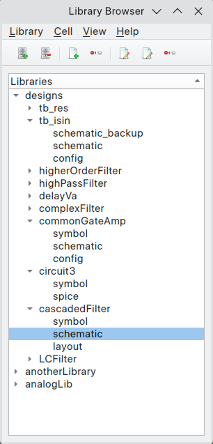
Library Browser menubar includes four menus:
-
LibraryThis menu has again four items:Create/Open Lib…,Library Editor,Close Lib…, andUpdate Library…- A library can be created using
Create/Open Lib...dialogue, which will open a file browser. An existing library can be selected or a new folder can be created. Revolution EDA will create areveda.libfile to denote that it is a valid library. At the moment, it is an empty file. Library Editordialogue can be used to open existing design libraries as well as saving library paths in alibrary.jsonfile so that the next time Revolution EDA is started the user will not have to open the libraries again.Close Libdialogue is used to close a design library.Update Librarywill rescan the library paths to reconstruct the
- A library can be created using
-
Cellmenu item has two items:New Cell…is used to create a new cell. It starts a dialogue to choose the library cell will be placed and its name. In the file system, it creates an empty folder under the library folder.Delete Cell…starts a dialogue to choose which cell will be deleted. When a cell is deleted, its child cellviews are also deleted. This is not reversible unless a revision control system is in place.
-
Viewmenu item has three items:-
Create New CellView...dialogue is used to create a new cell view.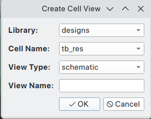
The following cellviews are functional at the moment:
Cellview Tool schematic Schematic Editor symbol Symbol Editor config Config Editor veriloga Text Editor pcell Text Editor spice Text Editor layout Layout Editor -
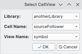
Open CellView...menu item is used to the start the relevant tool for a cellview. -
Delete CellView…menu item is used to delete a cellview.Both of these items will lead to a dialogue to select the right cellview:
-
Contextual Menus
There are also contextual menus defined for library, cell and cellview items in the Library Browser. Selecting an item and clicking right mouse button will display the relevant menu:
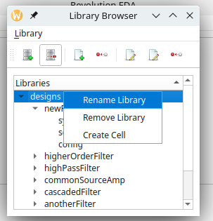
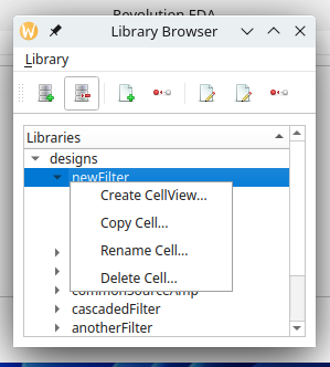
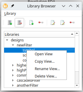
Their function are the same as the relevant menu item under Library menu.